When you have circuits that have continuous voltages, a multimeter is a tool that’s used to measure a single number for the voltages. However, this becomes very redundant when you start working with more complex circuits. This is where an oscilloscope proves to be very handy. But what is an oscilloscope?
An oscilloscope is a device that displays graphs of an electrical signal. The device allows you to see how voltages change over time; these voltages are also known as signals and used to convey information like how an audio signal plays music on a loudspeaker – the X-axis (horizontal) represents time and the Y-axis (vertical) represents voltage. At times, there is also a Z-axis that signifies the brightness or intensity of the display. In the case of DPO oscilloscopes, the Z-axis represents the display’s color grading.
With the help of this graph, you will be able to determine whether the behavior of your circuits are working normally and also locate any problems like unwanted signals known as noise.
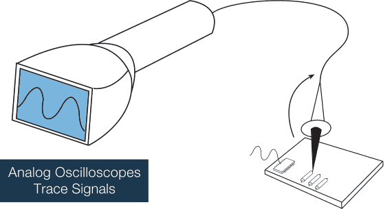
There are two primary types of oscilloscopes – analog and digital devices. As the name suggests, an analog oscilloscope will make use of high-gain amplifiers to display the waveform on a green cathode ray tube or CRT screen. In simpler terms, analog oscilloscopes are the older models of the device that was first developed in the 1940s.

An analog oscilloscope is fitted with a CRT module, a time base, a trigger system, a horizontal channel, and one of the many vertical channels; the vertical channel includes an analog delay line, a pre-amplifier, an attenuator, and the vertical amplifier that will amplify the signal to the required level for the CRT model.
On the other hand, the horizontal channels are fitted with two work modes – internal and external. Additionally, the trigger system allows you to adjust the levels between increase and decrease.
As the name suggests, a digital oscilloscope is a modern version of the analog oscilloscope and features a modern LCD screen; in fact, almost every oscilloscope manufactured today are digital.
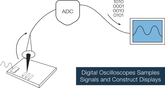
In the case of digital oscilloscopes, there is an extra step that takes place before the signal is displayed on the LCD screen. This extra step is the ADC (analog-to-digital) converter that converts the analog signals to digital information.
Overall, this reduces the device’s complexity and also makes room for more features. For instance, you will find that most digital oscilloscopes are fitted with features like complex mathematical operations and signal manipulation.
All types of oscilloscopes
There are several types of oscilloscopes, including:
- Analog Oscilloscopes: This type of oscilloscope uses analog circuits to process the electrical signals and display the waveform on a cathode ray tube (CRT) screen. They are commonly used in older systems, but are becoming less popular with the advent of digital oscilloscopes.
- Mixed Signal Oscilloscopes (MSOs): This type of oscilloscope combines the features of a digital oscilloscope with those of a logic analyzer, allowing you to analyze both analog and digital signals in the same instrument.
- Waveform Generators: This type of oscilloscope is used to generate electrical signals for testing and troubleshooting purposes.
- Digital Oscilloscopes (DSOs): This type of oscilloscope uses digital circuits to process and display the electrical signals. They offer higher accuracy, greater versatility, and more advanced features than analog oscilloscopes, such as the ability to store waveform data for later analysis. Here you can find best digital oscilloscope.
- Portable Oscilloscopes: This type of oscilloscope is designed for field use, with compact size and battery-powered operation. Find more information about Portable Oscilloscopes.
- PC-Based Oscilloscopes: This type of oscilloscope uses a personal computer to process and display the electrical signals, with the scope hardware connected to the computer via USB or other interface.
Each type of oscilloscope has its own strengths and weaknesses, and the best type for a particular application depends on the specific needs and requirements of the user.
What is an oscilloscope used for?
The uses of an oscilloscope are married and here you can check how to use an oscilloscope. The most common use of the device is to diagnose malfunctions in electronic equipment and allows technicians to understand the behavior of the voltage over time, i.e. whether it’s oscillating or not. You can also use the oscilloscope to see the time signals of a signal and its shape, which can prove to be very important in some applications. The oscilloscope can also be connected independently to each component to determine which ones are working and which are failing.
Oscilloscopes are often used to check electronics. When new equipment is designed, it is tested several times with an oscilloscope to find where a design flaw is or has been occurring. Additionally, there are also more advanced oscilloscopes that will store the variation of the signal for a long time, thereby allowing you to analyze the data any time later.

Oscilloscopes also have two more functions – sampling and triggering. Sampling is the process of converting a part of the input signal into discrete electrical values for different purposes like display, processing, and storage. The magnitude of each point being sampled is the same as the amplitude of the signal being inputted at the same time as it’s sampled.
The input waveform will look like a series of dots on the LCD of the oscilloscope. If the dots are spaced widely, it may make it difficult to interpret as a waveform. In this case, you can make use of the process known as interpolation, which connects the dots with vectors or lines.
Triggering is the process that will allow you to display and/or stabilize a repetitive waveform. Edge triggering is considered the most common type of triggering and consists of slope controls and trigger levels to provide the basic trigger point definition. The level control will determine on which point of the edge the trigger point will occur while the slope control will determine whether the trigger point is on the rising or falling edge of the signal.
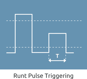
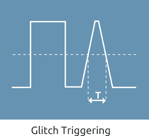


When you’re dealing with complex signals like pluses, pulse-width triggering may be needed. With the help of this technique, both the next falling edge and the trigger-level setting need to occur within a specific time gap. If these two conditions are met, it will trigger the oscilloscope.
Another type of triggering is the single-shot triggering. In this case, the oscilloscope will show a trace only when the signal of the input will meet the conditions of the set trigger. The oscilloscope will acquire and update the display and freeze the LCD to hold the trace once the trigger conditions are met.
What does an oscilloscope do?

A typical oscilloscope is fitted with four different types of systems – the trigger, display, horizontal, and vertical system. Each one of these systems will allow you to measure different things.
The vertical system will allow you to position and vertically scale the waveform; additionally, it can be used to set bandwidth enhancement, bandwidth limit, and input coupling as well.
The horizontal system will allow you to find the record length and sample rate, along with scaling and positioning the waveform horizontally.
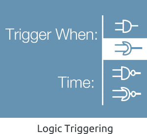
The trigger system can be used to stabilize repetitive waveforms and span a picture of the waveform. There are also different variations of trigger systems like threshold and edge triggering that responds to specific incoming signal conditions.
If you want to collect the data read by the oscilloscope, you will require a probe. A probe consists of two main parts – the probe tip and the ground clip. The ground clip is attached to the circuit’s ground reference and the probe top can be used to poke around and measure the voltages at different points throughout the circuit.
An oscilloscope can be used for looking at all kinds of signals in several different ways. If you study electronics, you will be able to use the device to watch how the signals change in circuits over time. You can also locate faults in equipment like radios, televisions, etc. A typical oscilloscope is also fitted with probes that will let you feed in the electric currents into the device with the help o coaxial cables – however, this doesn’t mean that an oscilloscope can only be used to measure electricity.
You can also plug a transducer (a device that converts one type of energy to another) and then use the oscilloscope to measure almost anything you want to. For instance, you can connect a microphone (a transducer that converts sound energy into an electrical signal) to understand and study sound signals with the help of an oscilloscope. Or, you can also connect a thermocouple transducer (for converting heat into electricity) or a piezoelectric transducer (a device that generates electricity squeezed) to study temperature changes or vibrations like heartbeats, respectively.
What does an oscilloscope measure?

An oscilloscope is an electronic test device that’s used to display electrical signals graphically; in most cases, the voltage is represented by the Y-axis (vertical), the time is represented by the X-axis, and (sometimes) brightness of the waveform is done on the Z-axis. You will also find some applications where the vertical axes can be used for current and horizontal axes that can be used to measure other types of voltage or frequency.
Oscilloscopes can also be used to measure the response to physical stimuli like heat, light, pressure, mechanical stress, and sound in the form of electric signals. Physical phenomena like electrical, temperature, and vibrations can be converted into a voltage by a sensor. For instance, a medical researcher can use the oscilloscope to measure brain waves while a television technician can use this device to measure signals from a television circuit board. A portion of the wave that repeats makes one cycle of the wave.
Oscilloscopes can also be used for measuring applications like:
- Observing noise on a signal
- Observing whether the signal is alternating current (AC) or direct current (DC)
- Measuring the time between two different events
- Measuring the signal’s frequency
- Measuring the signal’s amplitude
- Observing the signal’s wave shape
A typical oscilloscope is also fitted with different controls that will help you analyze waveforms on a graticule, which is a graphical grid. The graticule can be divided into divisions along both vertical and horizontal axes. These divisions will allow you to determine the waveform’s key parameters.
In the case of a digital oscilloscope, it will allow you to acquire a waveform by habituation the analog vertical amplifier’s signal of the input, sampling the signal of the analog input, change the samples to a digital form via ADC (analog-to-digital), store the digital data (sampled) in its memory, and reconstruct the waveform on your LCD.
How does an oscilloscope work?
Since there are two types of oscilloscopes, we’ll explain separately how analog and digital oscilloscopes work.
When you connect an analog oscilloscope to the circuit, the voltage will travel through the probe to the vertical system. The attenuator will reduce the voltage of the signal or an amplifier will increase the voltage of the signal, depending on how you set the vertical scale. Then, the signal will travel directly to the vertical deflection plates of the CRT (cathode ray tube). When you apply voltage on the deflection plates, the glowing dot will start to move. A positive voltage will cause the dot to move upward, while a negative one will move the dot down.
This signal will also make the trigger system perform a horizontal sweet, which will cause the glowing dot to move across the screen. When the horizontal system gets triggered, the glowing dot will move across the screen, from left to right. At the highest speed, the dot may sweep across the screen as many as 400,000 times.
With the vertical deflection action and the horizontal sweeping action, a graph will be traced on the screen.
When it comes to digital oscilloscopes, the working of these devices is almost similar to their analog counterparts. However, digital oscilloscopes are often fitted with additional data processing systems that will help you collect more data efficiently in an entire waveform and then show it on the LCD.
When you connect a digital oscilloscope to the circuit, the vertical system will adjust the amplitude of the signal, similar to an analog oscilloscope. Then the ADC (analog-to-digital convertor) will sample the signal along with discrete points and convert the voltage to digital values known as sample points. The sample clock of the horizontal system will determine how often the ADC will take a sample. The sample points from the ADC are stored up in the device’s memory in form of waveform points. It takes more than a single sample point to make up one waveform point.
Why the larger waves are seen on the oscilloscope?
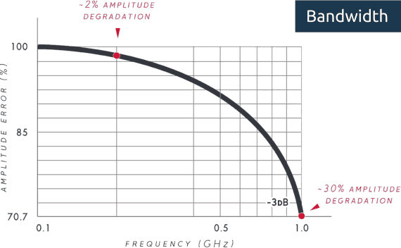
The bandwidth will determine the oscilloscope’s functionality to measure a signal. As the frequency of the signal increases, the oscilloscope’s capability to accurately display the signal goes down. This specification will indicate the frequency range that the device can measure with the utmost accuracy. According to IEEE 1057, electrical bandwidth as the point at the sine wave’s amplitude is reduced by 30% (or 3dB). In short, the bandwidth is specified at the frequency at which the attenuation of a sinusoidal input signal is 70.7% of the true amplitude of the signal.
The most optical bandwidth of an oscilloscope can be defined as the frequency of the power coming out of the same system is one half in contrast with the nearby direct current frequency. Therefore, the optical bandwidth will correspond to the bandwidth of traditional electrical circuits of -6dB.
Another explanation why the larger waves are seen on the oscilloscope is that the larger waves seen on an oscilloscope are often due to higher voltage levels in the electrical signal being measured. Voltage is a measure of the electrical potential energy in a circuit, and a larger voltage level means that the electrical energy is higher. The waveform on the oscilloscope reflects the changes in voltage over time, so if the voltage level is higher, the waveform will appear taller on the oscilloscope display.
Additionally, the size of the waveform can also be influenced by other factors, such as the frequency of the signal and the impedance of the circuit. For example, a higher frequency signal will have smaller, faster-moving waveforms, while a lower frequency signal will have larger, slower-moving waveforms. The impedance of the circuit can also affect the size of the waveform, as a higher impedance will result in a smaller waveform, and a lower impedance will result in a larger waveform.
Overall, the size of the waveform seen on an oscilloscope can give you important information about the electrical signal being measured, including the voltage level, frequency, and impedance of the circuit.
Oscilloscope Epic Growing FAQ
The best definition of an oscilloscope
An oscilloscope is an electronic measuring instrument that displays voltage signals as a continuous waveform over time. It allows you to visualize and analyze the electrical signals in your circuit, including the voltage and frequency of the signal, as well as other characteristics like amplitude, rise time, and more. Oscilloscopes are commonly used in electronics design, troubleshooting, and testing, and can provide valuable information about the behavior of your circuit.
The best definition of an oscilloscope for a kid
An oscilloscope is like a special tool that helps you see how electricity is moving in a circuit. Imagine you’re playing with a ball and you want to see how high and fast it’s going. An oscilloscope can show you the same thing, but instead of a ball, it’s looking at the electricity in your circuit. It helps you see how much electricity is flowing and how fast it’s moving. This is helpful when you’re building or fixing things with electronics because it can help you make sure everything is working correctly.
The best explanation of how an oscilloscope works
An oscilloscope works by measuring the voltage of an electrical signal over time and converting that information into a graphical display. The oscilloscope has two main parts: an amplifier and a display. The amplifier takes the electrical signal and makes it stronger, so it’s easier to see on the display. The display is like a screen that shows you the changing voltage of the signal over time.
When you connect your circuit to the oscilloscope, it sends the electrical signal to the amplifier, which amplifies it and sends it to the display. The display shows the voltage of the signal as a waveform, with time on the horizontal axis and voltage on the vertical axis. The waveform helps you see the changes in the voltage over time, and it gives you information about the frequency, amplitude, and other characteristics of the signal. You can also adjust the settings on the oscilloscope to zoom in or out, change the time scale, or measure specific values on the waveform.
The best explanation of how an oscilloscope works for a kid
An oscilloscope is like a special helper that helps you see the electrical signals in your circuits. It’s like having a special kind of x-ray for electricity. The oscilloscope has two parts – one part that makes the electrical signals stronger so it’s easier to see, and another part that shows you the signals as a picture on a screen.
Think of it like you’re playing with a bouncy ball and you want to see how high it bounces. You could use the oscilloscope to help you see how high the ball is bouncing and how fast it’s moving up and down. The screen would show you the changes in the ball’s height over time, just like the oscilloscope shows you the changes in the electrical signals over time. And just like how you can use your eyes to see how high the ball is bouncing, you can use the oscilloscope to see how high the electrical signals are bouncing in your circuits.
What Is An Oscilloscope – Conclusion
Did you like our What Is An Oscilloscope article? I hope this information helped you gain knowledge about an oscilloscope as it helped me. Today, oscilloscopes are widely used as electronic test equipment and the information in this blog post will help you get started. If you have any questions regarding this topic, you can leave your comments in the comment section below. And, don’t forget to share the blog with your friends and family.