Debugging an embedded system is a very difficult venture, especially when communication interfaces are involved. The smallest timing offset between signals between receiving a signal. Hence, monitoring these communication signals becomes important to ensure that you are able to see the message content and signal timing when you are developing a new interface or a driver.
One of the many tools that can help you do this is using a logic analyzer. In this article, we will help you understand what is a logic analyzer and its uses/functions.

Before we get into the details about a logic analyzer, let us understand its history. These devices were developed to be able to debug and look into faults on systems based on microprocessors.
When microprocessor chips were first developed around the 1980s, there was a need to develop methods that allowed monitoring test points and lines at the same time. While oscilloscopes were available (the analog ones), they could not be used for the job.
After the first development of logic analyzers, the complexity o the circuits could be tested. As time passed, the speeds rose, the number of channels increased, and more functionalities were added, like triggering.
What is a logic analyzer?

A logic analyzer is an instrument that is widely used for testing complex logic or complex circuits. These devices are perfect for people that want to understand and investigate the working and operation of these circuits.
Of course, oscilloscopes are capable of performing most of these functions; however, a logic analyzer will also display the relative timing of a large bundle of signals.
Basically, this device will allow you to trace logic signals in such a way that the overall operation of several signals in a digital circuit can be investigated and/or monitored.
However, most modern oscilloscopes are fitted with the same functionalities of a logic analyzer, thereby making them mixed-signal oscilloscopes.
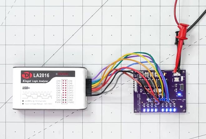
Logic analyzers are available in a wide range of formats. While you can obtain those that make use of traditional test equipment cases, there are many others that can be linked to your computers and laptops to offer you more processing power and flexibility.
It is obvious that most people tend to get confused between oscilloscopes and logic analyzers. Technically, the confusion is right, since both devices are almost similar to one another. However, you need to compare both devices so that you understand the differences between them.
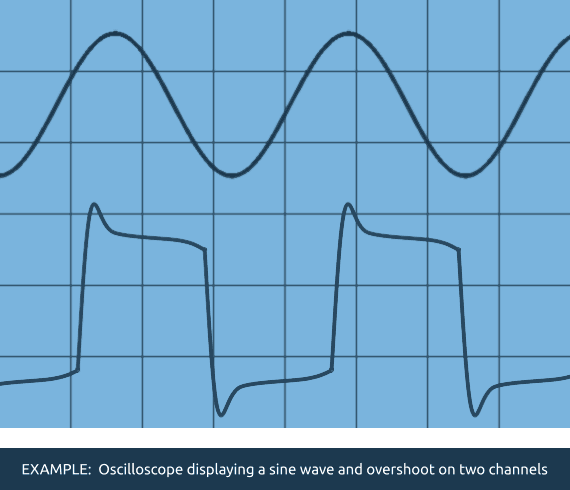
Oscilloscopes are tools that are mostly used for a general-purpose viewing of the signals. Thanks to the high bandwidth and sample rate, oscilloscopes will allow you to capture a lot of data points over time, measuring small time increments, transient events, and signal transitions (also known as edges).
While an oscilloscope might look into the same digital signals as a logic analyzer, they are mostly used for measuring analog events like the elapsed time between edges, peak amplitudes, and rise/fall times.


Additionally, oscilloscopes have only four input channels. While this is enough, it can present a problem if you want to measure more than five signals at the same time or you are using a digital system with a 32- or 64bit data bus. You would then require a device with more inputs.
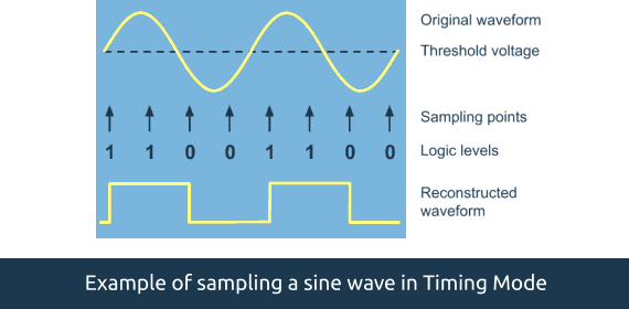
On the other hand, logic analyzers are not used to measure analog events. Instead, the device is used to detect logic threshold levels. A logic analyzer will primarily look for two logic levels – when the level is below the threshold voltage (Vth), it will be said as ‘0’ or ‘low’. Alternatively, if the level is above the Vth, the sample will be stored as ‘1’ or ‘high’.
Logic analyzers also have more inputs than oscilloscopes – between 34 and 136 channels. Each of these channels signifies a single digital signal. There are also some complex logic analyzers that offer more than a thousand input channels.
Logic analyzers are designed to monitor a large number of signals. They are optimized to monitor many digital circuits and can also have more than 200 channels. However, there are also specialized devices that can handle more than 200 lines, thereby allowing you to look into complex computing systems.
What do I need a logic analyzer for?
There are several reasons why you would need a logic analyzer, thanks to the wide range of benefits it provides. Some of these include:
Recording several input channels simultaneously
Perhaps the most important benefit of these devices is that the device can easily record a lot of digital signals at the same time – at times, even up to 100 channels at a time, depending on the model. While oscilloscopes can also record digital data, they cannot be used to record this many signals at the same time due to the memory requirements for storing analog data.
Complex digital triggering
Logic analyzers, similar to oscilloscopes, can be configured to start recording on a particular trigger event. These triggers can range from something as simple as the rising or falling channel edge or a complicated set of conditions that includes the states and edges of multiple channels.
Mixed-signal capabilities
Most modern logic analyzers are fitted with some functionality of oscilloscopes and vice versa. With the help of these upgrades, the device becomes capable of recording and analyzing analog as well as digital waveforms, or also known as mixed-signals. With the help of this equipment, you will be able to use the analyzer for multiple purposes and make complex and characterizing systems and circuits easier.

Portability
Most logic analyzers today are fitted with screens that will display the data of the captured signal. However, since computers and laptops have become more powerful and fitted with faster peripheral ports like USB 3.0, some of these devices have completely removed the screen and rely on dedicated software for the analysis. This will save up on costs and size.
Faster digital measurements
Modern logic analyzers and dedicated software contain a lot of different features that will help you characterize different signals. This includes the measuring aspects of the signal like period of periodic signals, frequency, pulse width, and even duty cycle.
If you wish to analyze the transmission data between two signals, a logic analyzer will prove to be a great help when it comes to timing analysis. For instance, the data line (SDA) with the I2C needs to be placed at its intended value for a certain time period before rising the edge of the clock line (SCL). This is called the setup time. The SDA also needs to be held at the intended value for most other implementations of I2C until the subsequent falling edge of the SCL, or also known as the hold time.
If the sample rate of the logic analyzer is fast enough, you will be able to measure setup and hold times with more accuracy. This way, you will ensure that the digital signals are being read properly by you or any other receiver.
Ease of data navigation
Most logic analyzers are capable of capturing digital data, storing the buffer, and then display it on the screen. Others show the signals in real-time, similar to an oscilloscope. While this feature is particularly helpful in looking for trends while a system is operating, it can be cumbersome to search and look for the details related to the signals.
Any type of logic analyzer, whether standalone or attached to your laptop/computer, will include dedicated software that will help you navigate through this humongous pile of signal data. This includes searching, panning, and zooming.
Decode and look for transmitted data
One another interesting aspect of logic analyzers is their ability to decode signals. Most of the modern digital communication systems are executed based on some protocols. Logic analyzers and dedicated software can also make use of these protocols so that you make sense of the data that is being captured.
With the help of recorded data, most logic analyzers will allow you to look through the data if you are searching for particular patterns. For instance, we can look into the bus address of the I2C, which denotes when the transmission is just about to start. Some devices will allow you to set a definite pattern for search, as the trigger condition to start the recording process.
When to use a logic analyzer?

The main function of a logic analyzer is to detect digital signals. Logic analyzers are very useful and attractive test instruments that can be used with complicated digital systems. Now, you can gain access to various test points and can also be used to debug IO and wide busses.
There are many potential measurements for a logic analyzer and can be used with a lot of computer systems like Raspberry Pi, Arduino, etc.
With the help of a logic analyzer, you will be able to correlate large collections of signals at once. You will gain a nice view of all the data that are being moved from one point to another and process different embedded systems within a computer.

For instance, logic analyzers can help you monitor the data that comes with the UART microprocessor. You will be able to look into all these busses over a time period, something that cannot be done by an oscilloscope. You can make use of a simple logic analyzer for a wide range of areas.
Logic analyzers are important testing pieces of equipment that enable developers and engineers to study what goes around in logic circuits. You will have a much better insight rather than using other test instrumentations.
How to use a logic analyzer?
While the use of a logic analyzer may seem complicated at first, there is a methodical approach that will allow you to set it up correctly and use it with full effectiveness. After you connect the probes, the logic analyzer will automatically name each signal.
Additionally, a logic analyzer can also be used to categorize different signals into groups so that they can be manipulated with ease.
How do you set up the capture mode in a logic analyzer?
For a basic setup, you will have to choose the capture mode. There are two different types of capture modes:
Timing mode: The signals are sampled at pre-defined intervals based on a clock (either internal or external).
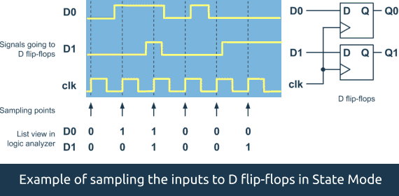
State mode: One or more signals are set up as clocks and the sampling of the data is based on the edges of these clocks.


How do you set up the trigger mode of a logic analyzer?
Once you have selected the capture mode, you need to set the trigger mode. In most logic analyzers, there are two types of trigger mode:
Pattern trigger
As compared to setting the slope and trigger level on an oscilloscope, setting the trace specification on a logic analyzer is very different. Most of these analyzers trigger on the pattern of the lows and highs across the input signals. This is equal to a certain pattern on a numbered data.
This is mostly set in decimal numbering, ASCII, octal, hex, and binary (1s and 0s). When you are looking at buses that are between 4- and 31-bits wide, using a hex format for defining the trigger point is especially helpful.
Edge trigger
When you adjust the trigger level control of an oscilloscope, it is almost the same as setting the level of a voltage comparator that gets triggered once the voltage of the input crosses the threshold level. Similarly, the working of a logic analyzer remains the same, except the trigger level is set already to the logic threshold. While most of the logic analyzers are level-dependent, the control signals and clock of these devices are often sensitive to the edge. This way, edge triggering will allow you to capture the data once the device gets clocked.
When the clock edge rises or falls to catch the outputs of the shift register, the logic analyzer will then capture the data. In most cases, the tracepoint will be delayed so that you can look into the propagation delay via the shift register.
What is a Logic Analyzer Epic FAQ
What is a logic analyzer in simple words?
In simple terms, a logic analyzer helps to understand how digital signals behave and interact with each other. It is often used by engineers and technicians to troubleshoot and debug digital circuits and systems, to verify the operation of digital components and communication protocols, and to perform functional testing of digital systems.
A logic analyzer is similar to an oscilloscope, but it is specifically designed for digital signals. Unlike an oscilloscope, which displays the analog waveform of a signal, a logic analyzer displays the digital state of the signals (high or low) and can provide information about the timing of the signals, such as the duration of a high or low state, or the time between two transitions.
What is a logic analyzer used for?
A logic analyzer is used for a variety of purposes in the testing and debugging of digital circuits and systems. Some of the most common uses of a logic analyzer include:
- Debugging digital circuits and systems: A logic analyzer provides a visual representation of digital signals, which makes it easier to diagnose and troubleshoot problems in digital circuits and systems.
- Verifying digital communication protocols: A logic analyzer can be used to verify the performance of digital communication protocols, such as I2C, SPI, and UART, by observing the waveform of the communication signals and analyzing their timing and state.
- Measuring performance of digital systems: A logic analyzer can be used to measure the performance of digital systems, such as the speed and efficiency of data transfers, by observing the timing and state of digital signals.
- Testing digital components: A logic analyzer can be used to test the functionality of digital components, such as memory chips, microcontrollers, and FPGAs, by observing the digital signals that they generate and receive.
- Debugging microcontroller-based systems: A logic analyzer can be used to debug microcontroller-based systems, such as embedded systems and IoT devices, by observing the digital signals that are generated by the microcontroller and other components.
What does it mean that logic analyzer in embedded system?
A logic analyzer in an embedded system is a tool used to analyze and observe digital signals in a circuit. It is commonly used in the development and debugging of embedded systems, as well as in digital electronics. The logic analyzer captures and displays signals in real-time, allowing engineers to visualize how digital signals change over time, identify timing issues, and pinpoint errors in the system. This helps in ensuring that the embedded system operates as intended and helps with troubleshooting when issues arise.
What is a Logic Analyzer – Final Word
You should use a logic analyzer in an embedded system if you want to: Visualize digital signals and how they change over time, Identify timing issues and errors in the system, Troubleshoot issues and ensure that the system operates as intended, Pinpoint the source of errors in a complex digital circuit.
A logic analyzer can provide valuable information and help streamline the development and debugging process, making it a valuable tool for embedded systems engineers and digital electronics professionals.
Did you like our What is a logic analyzer post? Don’t forget to check our other posts – Best Logical Analyzer might be interesting for you.


