In order to test your electronic devices, you need different types of instruments like voltmeter, ohmmeter, ammeter, etc. They can be used to test circuit properties like the voltage, resistance, and current to see if all the connections are correct.
For expert technicians, it is not enough to just read a testing instrument. You cannot connect an ohmmeter to a circuit for testing purposes if you have no idea how it operates. So What Is Ohmmeter?
An ohmmeter is a device used for measuring a material’s electrical resistance, which represents the opposition it presents to electric current flow. This instrument consists of a variable resistor, a meter movement that is calibrated in ohms, and a battery.
There are three main types of ohmmeters, and these are micrometers, teraohmmeters, and megohmmeters, and they are different from each other in regards to the resistance range they are able to measure.
The device indicates the resistance reading through a mechanical meter movement operating on an electric current. To produce the required current to operate the meter movement, there must be an in-built voltage source inside the ohmmeter. It must also possess ranging resistors that allow the optimum amount of current to pass through, regardless of the resistance.

Generally, ohmmeters have low accuracy. You can use it for a wide range of applications to find out the approximate resistance value. It can be used to determine the resistance of different parts of a circuit like a machine field coils, the heater element, circuit continuity, inspecting the semiconductor diodes, sorting and measuring of a resistor, etc.
Additionally, it has applications in academics as well. You can use it in a laboratory along with a bridge to know the approximate resistance value. This gives you abundant time to balance the bridge.
How does an ohmmeter work?

An Ohmmeter works according to Ohm’s Law which says that the steady current flowing through the resistor is directly proportional to the voltage difference across its ends. The mathematical representation of Ohm’s Law is V=IR.
If you wish to determine a conductor’s resistance, you need to connect the black and red wires to the negative and positive terminals. The device has a needle that shows the resistance of the circuit or the wire.
The deflection of the needle depends on the battery current. At first, you must short together the leads to measure the circuit’s resistance. After doing this, you can alter the meter for the required operation in a specific range and the needle goes to the maximum value on the scale and the meter current is at maximum.
After you are done testing the circuit, you must remove the test leads. The battery loses charge when the leads are joined with the circuit. When the test leads are shorted and the necessary adjustments are performed on the rheostat, the needle returns to zero. This indicates that there is no resistance between the leads.
How to use an ohmmeter?
Here are the steps you need to follow in order to measure resistance using an ohmmeter:
1. Setting up your instrument
Step 1
First, you need to make sure the Ohmmeter is plugged in or has a battery inside. Most Ohmmeters come with a battery that is in-built or separately packed along with instructions for installation. Regardless of whether your device is analog or digital, you’ll need to complete this step.
Step 2
The next step requires you to connect the test leads to the right sockets. The black lead should be connected to the negative slot while the red leads go into the positive plug. You must plug the short ends into the sockets because the longer ends are used to test the resistance of a circuit.
Step 3
The third, you need to do the zero adjustments by touching the two lead ends together. As you bring them together, the ohmmeter’s needle should point rightward. If this doesn’t happen, you need to shift the adjustment knob until when the needle reaches 0 while the leads are still in contact with each other.
Unlike most of the normal measuring scales, the ohmmeter scale displays the reading in the reverse direction. This means that the resistance value decreases as the needle moves towards the right and increases as it moves towards the left. If you are using a digital ohmmeter for measuring the circuit or wire, then the reading on the screen should be zero when you connect the two leads.
Step 4
If it’s possible, you should test out your ohmmeter on a regular resistor brought from the store. You should get yourself a resistor where the value of resistance is already mentioned. Next, calculate this resistance using the ohmmeter and check if the two readings match.
To test the ohmmeter, you can use plenty of other things apart from the resistor, like a mark made with a graphite pencil on paper, or a strip of aluminum. But of course, you have to know the resistance value beforehand. You can do this by placing the leads of the ohmmeter on the conductor’s either end and check if the screen shows the proper resistance value.


2. Measuring the resistance
Step 1
Make sure there is no power flowing into the circuit. Disconnect it completely from the power source or turn it off. The circuit or wire you are measuring must be completely dead because otherwise the measurement may be inaccurate and you can suffer from an electric shock as well.
Since the Ohmmeter acts as a source of power supply current and voltage to your circuit, you don’t need any other source of power. If you conduct the test on a powered circuit, it can damage the circuit, the device, as well as yourself.
You should always make sure you are not testing on a live circuit. In some cases, it is not enough to just cut off the source of power. If the circuit has capacitors in it, it will take some time to discharge. If the electronic device is based on cathode ray tubes, like in the case of a television or if it is a microwave oven, you need to exercise caution and wait for a while before you can start testing the circuit.
Step 2
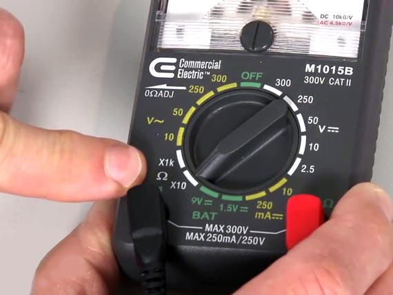
Next, you need to adjust the device to the proper scale. You can use the dial to make this adjustment, turning it in the center to adjust the scale, starting from 10s, to 100s, to 1000s, and so and so. As a best practice, you can adjust the meter to a scale that is just above the resistance of the circuit being measured.
For instance, if the circuit to be measured has an expected resistance of a few thousand, you need to adjust the ohmmeter scale to the 100s. As such, if the reading is “12”, you can say that the resistance of the circuit is 1200 ohms. Of course, you need to have a rough idea of the resistance value in order to adjust the scale.
Step 3
After this, you should place the two probes at either end of the circuit you are measuring. You can connect a probe to either end and it wouldn’t make any difference as far as the resistance reading is concerned.
This is because you will be measuring the resistance, the value of which remains the same regardless of the direction of flow of current. You can place the positive and the negative probe on any end to get the proper resistance value.
Step 4
This step involves determining the resistance of the circuit by reading the number on the device. Then you have to multiply this number by the scale that you’ve set your meter to, and you will get a value that equals the resistance of the circuit.
With decreasing resistance, current can flow more easily through the electronic circuit. So a circuit having a resistance of 0 ohms would allow current to flow through it unobstructed.
Step 5
If you wish to measure the resistance values for the different small components of a circuit, then individual testing needs to be performed for them. If you wish to test a particular resistor attached to the board, you can extract it using a soldering iron.
This is to make sure that there is no accuracy in the reading owing to interference from another component in the circuit. To put it another way, if you use an ohmmeter to test a resistor that is still attached to the circuit board, there is no way for you to make sure that the resistance value shown in the reading is only from that specific resistor.
Step 6
After you’re done measuring the resistance, you should turn off the ohmmeter. If you store the device without turning it off, the test probes are prone to get shorted, which would drain the battery. You can avoid this by disconnecting all the wires and turning the device off before keeping it aside.
How to read an ohmmeter?
In order to take a reading using an ohmmeter, first, you need to set its range by turning it on and turning the dial located on the front. If you have no idea regarding the resistance range of the resistor to be measured, you should begin from the highest setting in the megaohm range and reduce it gradually till you get a reading on your ohmmeter.
If you are working with an ohmmeter having a needle display, the needle will move towards the middle. In case the needle lies close to either end, you should change the range until the point you can see it lying near the full range.

If the device is using a D’Arsonval display, there is likely to be a reflective arc lying beneath the numbers. You should adjust the meter or your head till the scale is right in front of you and all you can see is the needle. If instead, you see its reflection that would mean you are viewing it at a slight angle and cannot spot the needle’s exact position.
While you are looking straight at the scale, find out where along the scale the needle lies. There will be many different scales and you need to ensure that you are reading the needle’s position correctly. The needle will show the resistance value of the resistance being tested.
What is ohmmeter scale?
The ohmmeter scale is the range of resistance values that an ohmmeter can measure. Most ohmmeters have a scale that is calibrated in ohms, which is the unit of resistance. The scale typically covers a range from a few ohms to several megaohms, with the exact range depending on the type and model of the ohmmeter.
The scale usually has a number of divisions marked on it, with each division representing a specific resistance value. The position of the pointer on the scale indicates the resistance being measured. The accuracy of the ohmmeter depends on the accuracy of the scale and the calibration of the instrument.
How to test a transformer with an ohmmeter?
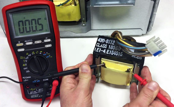
If you are using an ohmmeter to test an AC transformer, you need to measure the resistance of the coiled wires lying near the core. Then you touch the leads to either end of the wiring and read the resistance value shown in the display.
Check if this value is the same as that mentioned on the datasheet of the transformer. If the difference between the readings is quite large, it is quite probable that there is something wrong with the transformer and so you should replace or remove it immediately. Just to be sure, you can conduct the test 3-4 times since the readings are not always accurate.
How to test a capacitor with an ohmmeter
For this purpose, you can use a digital or analog device. Take it to the highest ohm range, at least in the thousands. At this point, a small amount of current is generated by the meter when you connect the leads to the opposite ends of the capacitor. After you connect the leads, you should keep them there for a few seconds.

In the case of an analog meter, the needle will start rising from a low value, climbing steadily as the charge accumulates in the capacitor. This will happen provided the capacitor is working properly. Otherwise, the needle will remain in the same position.
In the case of a digital ohmmeter, a good capacitor will cause the reading on the display to rise slowly until the capacitor gets discharged. After that, the value will go back to 0 and start rising again. In case of a bad capacitor, the resistance value will be extremely low and it will remain unchanged.
What Is Ohmmeter Epic FAQ
What is an ohmmeter?
An ohmmeter is an electrical instrument used to measure the resistance of a conductor or material. It is usually used to test the continuity of electrical circuits and to determine if the resistance of a component falls within the specified range.
What is an ohmmeter in simple words?
An ohmmeter is a tool that measures how much electricity can flow through a material. Think of it like a special ruler for electricity! It helps us see if an electrical circuit is working properly, just like how a regular ruler helps us measure how long something is.
How does an ohmmeter work to measure resistance?
An ohmmeter works by passing a small electrical current through the material being tested and measuring the voltage across it. The resistance of the material is then calculated from the ratio of voltage to current, using Ohm’s Law (V = IR). The ohmmeter displays the resistance value on its display. The resistance measurement helps determine if the material is a good conductor or if it has a high resistance, which would indicate a problem in the circuit.
What is the purpose of ohmmeter?
The primary purpose of an ohmmeter is to measure resistance in electrical circuits and components. This measurement helps to determine the continuity and integrity of electrical circuits, identify broken or damaged components, and test the resistance of electrical conductors. The information obtained from an ohmmeter can be used to diagnose and solve electrical problems, maintain and repair electrical equipment, and ensure the safe and proper operation of electrical systems.
What Is Ohmmeter – Final Word
Ohmmeters are useful tools for a number of reasons:
- Testing Continuity: Ohmmeters are used to test the continuity of electrical circuits, which helps to identify if there are any broken or damaged components that need to be repaired or replaced.
- Diagnosing Electrical Problems: By measuring the resistance of various components in a circuit, an ohmmeter can help diagnose and solve electrical problems, such as a short circuit or an open circuit.
- Testing Conductors: Ohmmeters are used to test the resistance of electrical conductors, such as wires, to ensure that they are within the specified range and are functioning properly.
- Maintenance and Repair: An ohmmeter can help identify worn or damaged components in electrical equipment and systems, which is useful for maintenance and repair purposes.
- Safety: Ohmmeters help to ensure the safe operation of electrical systems by identifying any potential hazards, such as high resistance connections or faulty components, that could cause electrical shock or damage.
In summary, ohmmeters are versatile and valuable tools for electrical testing, diagnosis, and maintenance.
Did you like our article What Is Ohmmeter? Don’t forget to check other, what is an oscilliscope might be interesting for you.