For those who don’t know, QAM stands for Quadrature Amplitude Modulation and it is a combination of amplitude and phase changes to offer an additional capacity and is widely used for data communication. Quadrature Amplitude Modulation utilizes both amplitude and phase components to provide a form of modulation that is able to provide high levels of spectrum usage efficiency.
QAM has been used for some analogue transmissions including AM stereo transmissions, but it is for data applications where it has come into its own. It is able to provide a highly effective form of modulation for data and as such it is used in everything from phones to Wi-Fi and almost every other form of high speed data communications system.
Probably you have heard about HDMI QAM modulators, COAX QAM modulators or EDGE QAM modulators, in such cases QAM modulator functions as translators, helping convert digital packets into an analog signal to seamlessly transfer data.
Best QAM modulators – HDMI, EDGE, COAX and others
The cost will always depend on the components and such factors as the number of available channels, available frequency, supported formats and many others.
Due to the fact that different readers may have different tasks, in this article we will highlight not specific models, but manufacturers that you can trust and choose from their range.
So again, before you buy a QAM modulator it is important to understand what you need, what are the requirements, what problem must be solved. Knowing this input data the choice will not be so difficult.
Best COAX QAM modulator – Value for money
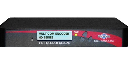
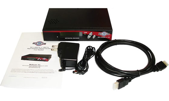
Multicom 1080P HDMI to Coax Digital 100 Encoder QAM Modulator
- Unencrypted HDMI input, RF QAM output
- Audio Compression: AC-3, MPEG-4 AAC, MPEG-1 Layer II
- Adjustable Attenuation
- RJ-45 port for web configuration
- Video resolution up to 1080p
- Perfect, clean, and clear picture on high motion video, sports, text crawls/rolls, etc.
Multicom manufactures high quality electronics that do their job perfectly.
The modulator we chose allows you to use a coax cable to transmit video in high resolution. With an HDMI source you can easily get up to 1080p resolution. The function of the modulator is very simple and allows you to connect it quite simply, which is always an advantage for simple modulators from Multicom.
Best professional HDMI QAM Modulator – Hiqh Quality modulator for challenging tasks
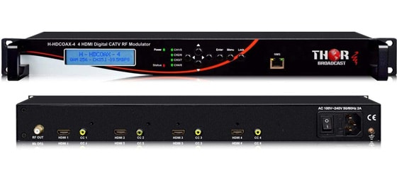
Thor Fiber 4 Channel HDMI Modulator QAM +ATSC Modulator with Closed captioning
- 4 HDMI Inputs HDCP compliant + 4 Baseband video inputs for 608/ 708 CC
- Creates any 4 individual CATV channels of your choice , excellent video quality
- Support QAM, ATSC, DVB-T, ISDB-t modulation type
- NMS etherent port for easy setup and monitoring
- Front panel LCD for setup and parameters display, AC3 Dolby Audio, MPEG2 Video encoding up ro 22Mbps
Thor Fiber is recognized as one of the industry leaders in the production of high-quality modulators designed for demanding tasks and often used by professionals. From components, to build quality, to available features and supported formats, Thor Fiber is always at the top of its game. This explains its popularity, but also its price.
The modulator we chose has several inputs and outputs and supports different formats like QAM, ATSC, DVB-T, ISDB-t modulation type. The line of this manufacturer is wide enough and you can always find QAM modulator for your task.
QAM Modulator & Demodulator
In any system that uses quadrature amplitude modulation, QAM, there will be modulators and demodulators.
These QAM modulators and demodulators must enable the ability to modulate both the in-phase as well as quadrature parts of the signal modulating on the carrier.
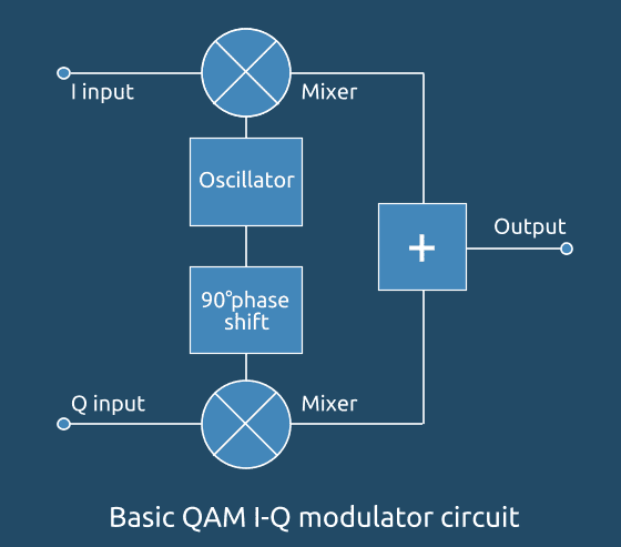
QAM modulator basics
The QAM modulator basically follows the concept that is apparent as a fundamental QAM theory, where there are two carriers with a shift of 90 degrees between the two. They are then amplitude-modulated using two data streams, known as The I or In-phase as well as The Q, or Quadrature streams. These are produced in the processing of baseband.
The two signals that result are then summed, and processed according to the signal chain of RF generally converting them to the desired final frequency, and amplifying them in the manner required.
It is important to note that because the amplitude the signal fluctuates, all amplifiers for RF must be linear to ensure its integrity. Non-linearities can alter the relative level of the signals, and also alter the phase gap which can distort the signal and increasing the risk of errors in the data.
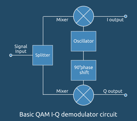
QAM demodulator basics
Its QAM demodulator is opposite to that of the QAM modulator. When the signals are received by the system, and they are split and then each one is fed to the mixer. One half of the signal has an local oscillator in-phase, while the other half is equipped with the quadrature oscillator applied.
The modulator’s basic assumption is both quadrature signal are exact in quadrature.
Another requirement is to create an oscillator local signal for demodulation that exactly matches the frequency required to be used for signal. Any frequency offset will result in an adjustment in the frequency of the local oscillator’s signal with regard to the two sidebands carriers that are suppressed from the signal overall.
Systems have the circuitry to recover carriers that usually uses an asynchronous loop. Some even have an internal loop and an outer one. The ability to recover the carrier’s phase is vital, as in order to ensure that it is possible that the error rates of the data could be affected.
The circuits in the above diagrams show the general IQ QAM modulator and demodulator circuits which are utilized in a large range of diverse sectors. They are not just comprised of discrete parts, however, they are often employed in integrated circuits that can be used to perform a wide range of functions.
What is QAM, quadrature amplitude modulation
Quadrature Amplitude Modulation QAM, is a type of signal where two different carriers that have been shift in phase by 90° (i.e. sine or cosine) are combined and modulated. Because of their 90deg differences in phase, they are quadratured and that is why they get the term. In most cases, one signal is referred to as the In-phase signal, or “I” signal, and another is the quadrature signal or “Q” signal.
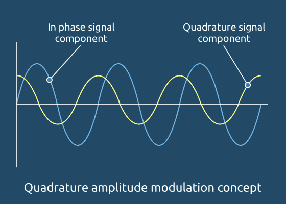
The resulting overall signal made up of the combined effect of Q and I carriers consists both phase and amplitude variations. Because of the fact that both phase and amplitude variations are evident, it can be regarded as a combination of phase modulation and amplitude.
A reason for the usage of quadrature amplified modulation comes due to the simple fact that an amplitude-modulated signals, i.e. double sideband, even when using a suppressed carrier, occupies more than twice that bandwidth as the signal modulating.
This is a huge waste of the frequency spectrum available. QAM can restore balance by putting two distinct double sideband suppressed carrier signals within the same spectrum as an regular double sideband supressed carrier signal.
Analogue and digital QA
QAM, or quadrature amplitude modulation is available in what can be called either digital or analog formats. Analogue variants of QAM are used to allow multiple analog signals to be transmitted on the same carrier. For instance, it is utilized for PAL or NTSC television systems.
The various channels offered by QAM permit it to carry elements of colour or chroma information. In radio applications, a technology called C-QUAM is utilized to broadcast AM stereo. These channels permit the two channels needed for stereo to be run through a single channel.
The digital formats that comprise QAM are commonly called “Quantised QAM” and they are increasingly being used for data communication, usually in the radio communication systems. Radio communications systems that range from wireless technology, such for example LTE by wireless systems like WiMAX and Wi-Fi 802.11 utilize a range of types of QAM and the use of QAM is expected to continue to grow in the radio communications field.
Digital / Quantised QAM basics
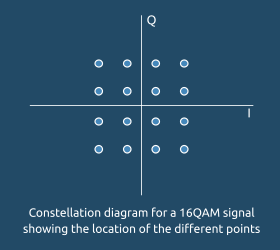
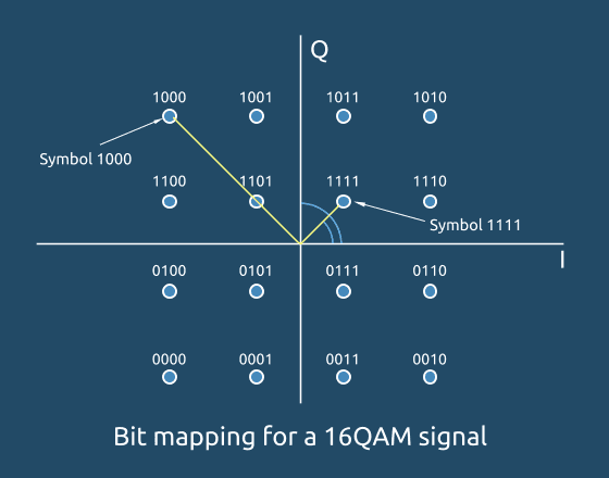
Basic signals only have two positions that allow for the transfer of number or a. With QAM there are a variety of points that are possible to use with defined values of amplitude and phase. This is referred to as a constellation chart. The various positions are assigned different values so that the same signal is capable of transferring data at a greater speed.
As you can see, constellation points are usually placed in a grid that has the same horizontal and vertical space. Even though data is binary, the most commonly used kinds of QAM however, not all, are when they can form an area with a number of points that is equal to the power of 2 i.e. 4, 16, 64 . . . . , i.e. 16QAM, 64QAM, etc.
With more advanced modulation techniques, i.e. the more points in the constellation, it’s possible to send higher amounts of data per symbol. But the points are more to each other, and therefore more susceptible to noise and mistakes.
The benefit of switching to high-order formats is they have more constellation points which means it can transfer more bits for each symbol. The disadvantage is that constellation points are closer which means that this link can be more susceptible to disturbances. This is why higher-order QAM versions QAM are only utilized in situations with a large signal to noise ratio.

The most common order of QAM that is encountered is 16QAM. The reason for this is the lowest order that is typically encountered is that 2QAM is same as binary phase shift keying, BPSK and 4QAM is identical to quadrature phase-shift keying or QPSK.
In addition, 8QAM isn’t extensively employed. The reason for this is that the error-rate performance of 8QAM is essentially exactly the same as 16QAM, but it is approximately 0.5 DB more efficient as well as the speed of transmission is three-quarters the rate of 16QAM. This is due to the rectangular, not rectangular shape, of the arrangement.
QAM advantages and disadvantages
While QAM is believed to boost the effectiveness of transmission in radio communications by utilizing both phase and amplitude variations however, it comes with a variety of disadvantages. One of them is that QAM is more susceptible to interference due to the fact that the states are closer and a lower amount of noise is required for the signal to be moved to a new decision point.
Receivers designed for use with frequency or phase modulation can both utilize limiting amplifiers which can eliminate any amplitude noise , and thus increase the reliance on noise. However, this is not the situation with QAM.
The other limitation is connected to the amplitude portion that the signal. If a frequency or phase altered signal gets amplified by radio transmitters it is not necessary to utilize linear amplifiers. When making use of QAM with an amplitude component, the linearity is required to be maintained. However, linear amplifiers are not as efficient and use up more power, which renders them less appealing for mobile applications.
QAM Theory and Formulas – the basic theory and relevant formulas
The fundamental QAM theory is designed to explain the workings of QAM the modulation of quadrature amplitude using mathematical formulas.
It is, however, possible to explain some of the fundamental QAM theories in terms of relatively straightforward equations that offer some understanding of what’s really happening inside the QAM signal.
QAM theory basics
The theory of Quadrature Amplitude says that both amplitude and phase changes within the QAM signal.
The fundamental method through how an QAM signal is created is to create two signals which are in 90 degrees the same phase and then add the two signals. This creates an output sound that’s the product of both waves. It is a particular amplitude which results from the combination of both signals as well as an amplitude that depends on the sum of both signals.
If the amplitude of one the signals is changed, it affects both the amplitude and the phase of the whole signal the phase shifting towards those of signals with greater amplitude.
There exist two radio frequency signals that could be modulated, they are known as the I In-phase signals and the Q Signals of Quadrature.
It can be seen that the I and Q components are represented as cosine and sine. This is because the two signals are 90° out of phase with one another.
Where f is the carrier frequency.
The resulting waveform is a regular signal, whose phase can be altered by altering the amplitude or both Q and I. This could also cause an increase in amplitude also. It is therefore possible to digitally modify the carrier signal by altering the amplitude of both mixed signals.
QAM Formats: 8-QAM, 16-QAM, 32-QAM, 64-QAM, 128-QAM, 256-QAM
QAM, or quadrature amplitude modulation, can provide significant advantages to data transmission. As 16QAM evolves to 64QAM, 64QAM transforms to 256 QAM, and so on more data rate are possible, however, at the expense of noise margin.
A lot of data transmission systems shift between the various order that include 8QAM, 16QAM, 32QAM, etc., depending on the connection conditions. If there’s a high margin in the noise, higher QAM orders can be utilized to get speedier data rates. However, when the link is weakening and the link becomes weaker, lower orders are utilized to protect the noise margin, and to ensure that the low bit error rate is maintained.
There is therefore a balance to be achieved between rate of data and the QAM modulation power, order and what is the accepted bit error rate. Further error correction may be implemented to prevent any degradation in link quality however this could also affect the speed of data transmission.
QAM formats and applications
QAM is utilized in numerous radio communication and data delivery applications. However, certain specific variations of QAM are utilized in particular applications and standards.
There is an equilibrium between data throughput as well as the signal to noise ratio needed. When the number of samples is increased, the order of QAM signal increases, i.e. going from 16QAM up to 64QAM and so on. the speed of data processing achievable in ideal conditions rises. The downside is that a greater signal-to-noise ratio is required to attain this.
In some systems, the modulation order format is predetermined, however, in other systems, where there is the possibility of a two-way link you can alter the order of modulation to get the highest performance for the link conditions. The degree of error correction utilized is also modified. This way, by altering the order of modulation, as well as the accuracy correction method, speed can be optimized while keeping the correct error rate.
In the numerous types of wireless and cellular technology, it is possible to change the order of QAM modulation as well as error correction in accordance with the connection conditions between both ends.
As the data rate has increased while the needs for the efficiency of spectrum has increased so is the difficulty of link adapting technology. Data channels are transmitted by the radio signal that is transmitted by cellular devices to allow rapid adaptation of the link in order to meet the current quality of the link and to ensure optimal speed of data transfer. While balancing the power of the transmitter, the QAM order as well as forward error correction for instance.
Constellation diagrams for QAM
The diagrams of constellations depict the various locations for the different states in various forms of QAM Quadrature Amplitude Modulation. As the frequency of modulation grows and so does the amount of points in the QAM diagram of constellations.
The following diagrams show the diagrams of constellations for a range of modulation formats:
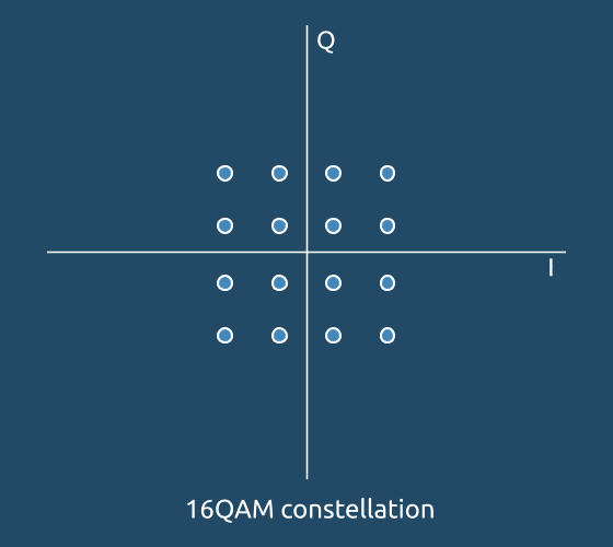
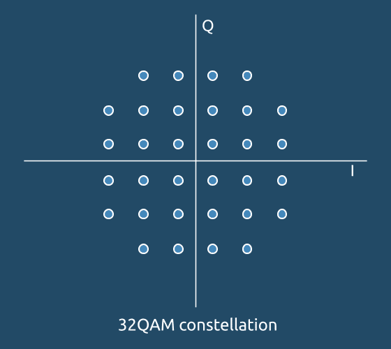

It is apparent from these a few QAM diagrams of constellations in that, as modulation rate increases, the distance between the points of this constellation diminishes. In turn, tiny amounts of noise could create more problems.
As the amount of noise rises due to weak signals and the space of coverage by a single point in the constellation expands. If the area becomes too big and the receiver becomes incapable of determining which point in the constellation the signal is intended to be. This causes mistakes.
It’s also discovered that the greater the degree of modulation of this QAM signal, the more the amount of amplitude variance is evident in the signal being transmitted. For transmitters with RF amplifiers, for everything from Wi-Fi to cell and beyond, it implies it is necessary to use linear amplifiers needed. Since linear amplifiers are not as effective than ones that can operated in saturation, this means that strategies such as Doherty amps as well as envelope tracking might be required.
Additionally, as the amplitude of the variation increases, the degree of efficiency declines. This is crucial for battery efficiency of mobile devices and power station efficiency.
QAM bits per symbol
The benefit of the use of QAM is that it’s an advanced form of modulation, and this means that it can carry more bits of data per symbol. If you select a higher-order QAM format the rate of data transfer of the link can be enhanced.
The table below provides the summary of bit rates of various types of QAM and PSK.
QAM Formats & Bit Rates Comparison |
||
|---|---|---|
| Modulation | Bits per symbol | Symbol Rate |
| BPSK | 1 | 1 x bit rate |
| QPSK | 2 | 1/2 bit rate |
| 8PSK | 3 | 1/3 bit rate |
| 16QAM | 4 | 1/4 bit rate |
| 32QAM | 5 | 1/5 bit rate |
| 64QAM | 6 | 1/6 bit rate |
Power spectrum as well as bandwidth effectiveness of QAM modulation is the same as M-ary PSK modulation, or in other words, with the same phase shift keying the power spectrum and the bandwidth efficiency levels are identical regardless of whether either quadrature amplitude or phase shift keying are utilized.
QAM noise margin
Although high order rates of modulation can be used to provide much more data speeds and greater levels of spectral efficacy for Radio communications, it is not without cost. Higher order modulation techniques are significantly less resistant to interference and noise.
In the wake of this, a lot of radio communications systems use dynamic adaptive modulation methods. They are able to detect the condition of the channel and adjust the modulation algorithm to achieve the best speed of data for the conditions.
Selecting the correct order of QAM modulation for a given circumstance, and having the ability to change it dynamically allows the maximum throughput to be achieved depending on the conditions of the link at the moment. By reducing the order of QAM modulation can allow smaller bit errors to be reached and decreases the amount of correction needed for errors. So, throughput can be maximized in line with the current link quality.
QAM Formats & Noise Performance |
||
|---|---|---|
| Modulation | ηB | Eb / No for BER = 1 in 106 |
| 16QAM | 2 | 10.5 |
| 64QAM | 3 | 18.5 |
| 256QAM | 4 | 24 |
| 1024QAM | 5 | 28 |
Did you like this post? Please let us know and don’t forget to check our other articles.
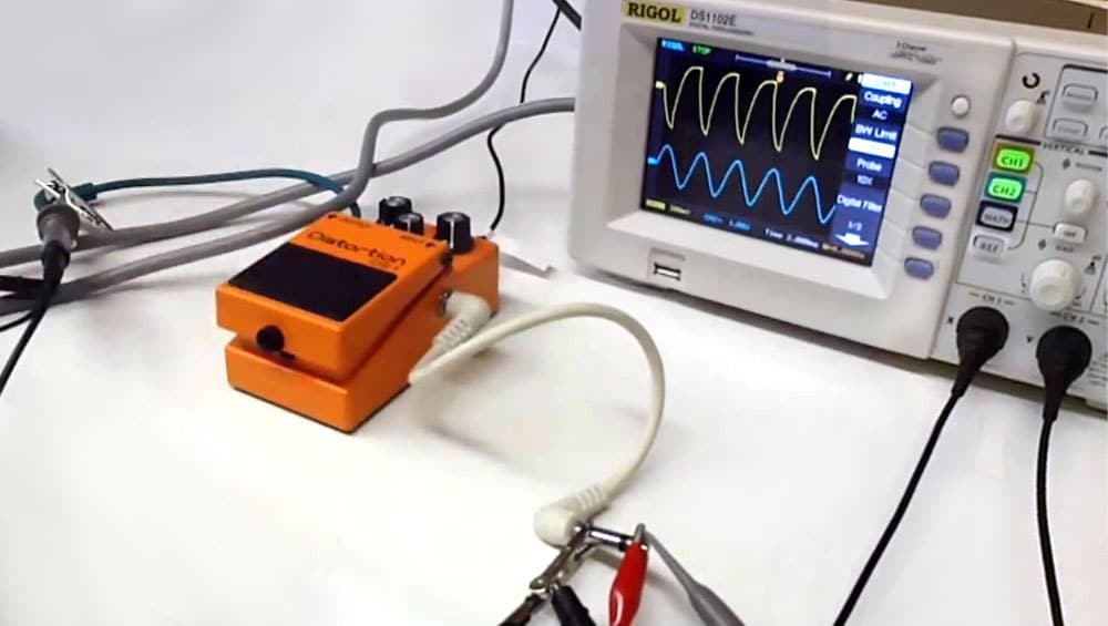
Digital Oscilloscope review – could be interesting for you!