For individuals working with electrical systems, it is vital to measure the current flow in a circuit or a contact. It tells them that the circuit is live and also allows them to calculate power consumption.
While such measurements were earlier hazardous and quite difficult, these days we have sophisticated instruments that allow for safe measurement of current. Here, we shall discuss one such instrument, known as the clamp meter. So What Is Clamp Meter?
A clamp meter or a tong tester is a reliable and safe testing instrument used for measuring a live conductor without damaging the circuit in any way or powering it down. Many technicians prefer this instrument because it lets them measure a strong current without having to power off the circuit being tested.
Clamp meters are mainly of three types, namely current transformer clamp meters, flexible clamp meters, and Hall Effect clamp meters.
When current flows through a circuit or a conductor, a magnetic field is created. This can be detected in order to find the value of the said current. It is safe and convenient to use for technicians since the current flow is not disrupted because of this.
Earlier, measuring in-line current was a bit of a hassle as you had to cut into the wire and place the measuring instrument’s test probes inside the circuit to do so. This device has a pair of transformer clamps, so you don’t need to bring it in contact with a conductor while taking measurements.
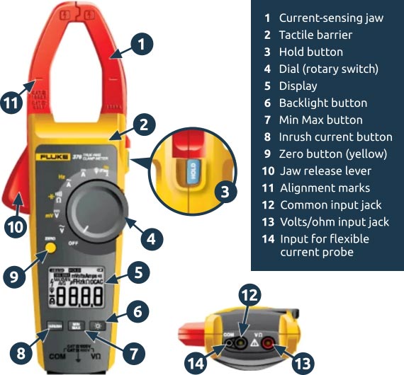
The different parts of this instrument are as follows:
- Jaws: These are also known as the clamps and they are used to detect the magnetic field formed due to the current passing through the circuit.
- Opening Trigger: This is a trigger used for opening or closing the clamps.
- Power Button: Used for powering the clamp meter up or down.
- Back Light Button: When you press this button, the LCD display lights up, thus letting you read the display in low light conditions.
- Negative Input Terminal: This is the terminal for connecting the meter cable’s negative jack.
- Hold Button: By pressing this button you can display the previous value.
- Positive Input Terminal: At this terminal, you can connect the meter cable’s positive jack.
- Functional Rotary Switch: You can use this switch to select the range and type of the measured current.
- LCD display: This is where the values are displayed.
How does a clamp meter work?
Let us look at the working principles for both current transformer and Hall Effect clamp meters.
Current Transformer Clamp Meter
The first type of clamp meter has a couple of clamps constructed with Ferrite Iron. Copper coils are wrapped around these clamps, resulting in the formation of a magnetic core. The instrument works on the electromagnetic principle that talks about magnetic flux being generated due to the flow of current through a conductor or a circuit.
Let us consider the conductor, through which the current is flowing to be the transformer’s primary winding. The flow of current creates a magnetic field in the conductor and when you place the clamp meter arm in order to measure the current, it forms the secondary arm of the transformer.
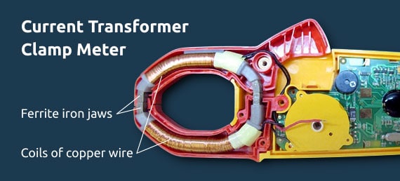
The clamp tester arm has an iron core that concentrates the conductor’s magnetic field. Due to this, a current is produced via electromagnetic induction and this is proportional to the primary current. The clamp tester’s arm is brought in contact with the circuit, after which we get the final value of the current.
The magnetic field that is formed in the clamps of the meter is proportional to the turn ratio. The clamp meter input receives a small current because the number of secondary windings is much higher than the number of primary windings.
For instance, take the number of secondary windings to be 1000. In this case, the secondary current is 0.001% of the primary current. Thus, it is possible to measure larger values of current by adding a few extra turns to the secondary winding. You have the option of converting the measured current into voltage since many instruments are now provided with an mV output.
Hall Effect Clamp Meters
You can use these types of clamp meters for measuring both AC and DC current up to the range of 1 kHz. Similar to the current transformer type clamp meters, these instruments concentrate the magnetic field encircling the conductor using solid iron clamps.

In this clamp meter, the clamps are not encircled by copper wires. Rather, the magnetic field is concentrated around the gaps in the iron core after you clamp the arms of the meter around the conducting material.
The gap is formed when the clamp tips of the instrument meet, thus creating an air pocket. This gap prevents the saturation of the core by limiting the magnetic flux.
Conversely, the clamps of a current transformer type clamp meter are level when they are closed. The clamp tips show the metal core when you open them. Inside the air gap, there is a semiconductor called the Hall Effect sensor, which is enclosed in a thin plastic covering. This is a sensor that reacts to magnetic fields by changing its output voltage.
Here the magnetic field is that of the conducting material or the circuit through which the current is flowing. The main objective of the Hall Effect sensor is to provide a direct measurement of the magnetic flux. Once you scale and amplify the output voltage produced by this sensor, you can get an accurate reading of the current that flows through the conductor.

In such devices, the direct current magnetic fields are focused around the core, similar to a piece of iron holding a permanent magnet.
Taking into consideration the earth’s magnetic fields and others lying in the vicinity, the reading must be zeroed before taking the final measurements. This allows you to get rid of the offset errors.
How to use a clamp meter?
You can use a clamp meter for measuring AC and DC current, voltage, and even resistance. However, before taking a measurement, you must make sure the test probes are not connected to the meter and that your fingers are placed behind the tactile barrier. This is a safety measure that will ensure you don’t suffer from an injury or electrical shock.
Measuring AC current through a flexible current probe
- You should not put the flexible probe around a live conductor or try to remove it from the conductor.
- Great care needs to be taken while fitting and removing the probe.
- The installation to be tested must be de-energized and protective gear should be worn if needed.
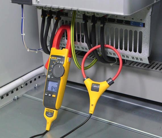
- First, attach the current lead to the clamp meter.
- The flexible tube of the probe should be connected around the conductor. Make sure to latch and close the flexible probe’s end after opening it for the connection. When the probe locks itself in place, you should hear a sound.
- When using the device to measure current, you need to center the conducting material and make sure no live conductors are lying nearby. The conductor should be kept at a minimum distance of an inch away from the probe coupling.
- Adjust the dial accordingly until the display indicates that the flexible probe is being used for taking the measurements. The same rule about the display flashing based on the current being less than or more than 0.5 A also applies here.
- Note the value of the current from the display.
In case the flexible probe is malfunctioning, you should check the coupling system for damage and ensure that it’s closed and connected in the proper way. The system will not get closed if there is an unknown material present. You should also check whether the dial is in the right position and whether the cable is damaged.
Measuring voltage using a clamp meter
These days, clamp meters can be used for measuring both AC and DC voltage. An electrician often has to take voltage measurements to fix electrical issues. This is a bit more complicated compared to measuring current since you need to involve the test probes instead of using just the clamps.
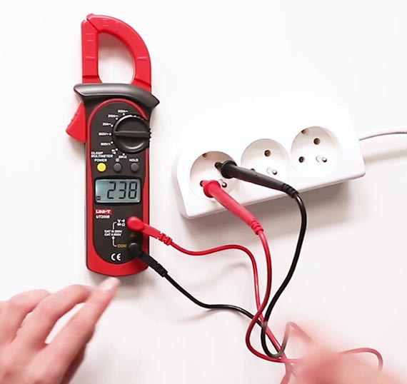
- Select the type of voltage to measure, i.e. DC or AC.
- Connect the test probes, connecting the black probe to the COM slot and the red probe to the V/O slot.
- Similar to current measurement, you need to select the voltage range to be measured.
- To get an accurate reading, you need to bring the probe tips in contact with the conducting material.
- If you wish to stay away from the source of electricity and recall the voltage reading at the same time, you can use the hold function. This freezes the reading, so you can put some distance between you and the electrical source without forgetting it.
Measuring resistance using a clamp meter
You must cut off power to the circuit before measuring the resistance because otherwise, you can damage it. In case the meter comes into contact with the voltage accidentally, some instruments have protective measures in place.

- Cut off power to the circuit.
- Adjust the dial to select resistance.
- Connect the black test lead to the COM input slot.
- Connect the red test lead to the VΩ input slot.
- Determine the part of the circuit whose resistance value you need to measure and connect the probe leads across it.
- Note the reading from the screen.
- Before you start taking measurements for resistance, you must ensure there is no power flowing into the circuit.
How to measure DC amps with a clamp meter?
- First, you need to set the dial to the right function, which in this case is A dc or A ac. In the LCD display, there should be an icon shaped like the clamps, which indicates that you are using the clamps for measuring the current.
When the current to be measured has a value less than 0.5 A, you can see the center dot in the clamp icon blinking, whereas when it is more than 0.5, the dot remains steady.
- Before you start taking the measurements for dc currents, you should wait until the display stabilizes itself, after which you need to press the zero button to make sure the readings are all correct. The purpose of zeroing is to eliminate any dc offset that might be present in the reading. This function is applicable only when you’ve adjusted the dial to A dc.
However, before you perform the zeroing, you must ensure the clamps are closed and that there is no conducting material in between them.
- Next, you need to release the jaws, open them, and place the conductor in between them.
- After that, you should close the clamps and bring the conductor in the right position as per the alignment marks.
- Note the measurement provided in the display.
- Convenience: Clamp meters are designed to be compact and portable, making them easy to carry and use in various locations. They are also equipped with a clamp that can be opened and closed around a conductor, allowing for hands-free measurement of current flow.
- Non-invasive measurement: Clamp meters can measure current flow without breaking the circuit or making contact with the conductor, making them a non-invasive testing solution. This is especially useful in situations where it may be dangerous or difficult to make direct contact with the conductor.
- Current measurement: Clamp meters are specifically designed to measure current flow in a conductor, providing an accurate and convenient way to measure current in a variety of applications.
- Multifunctionality: Many modern clamp meters are equipped with additional features, such as the ability to measure voltage, resistance, and continuity. This makes them a versatile tool for electrical testing and diagnostic applications.
If you have no idea regarding the measurement range, should set it higher than required, just to be on the safe side. Later, you can lower the range as you go along.
Nevertheless, the electrical conductor should not be running on a voltage greater than 600V. If there is too much voltage, you wouldn’t be able to take a reading using the clamp meter.

4 Reasons to Have Clamp Meter
Clamp meters can be extremely useful in a variety of electrical testing and diagnostic applications. Some of the benefits of using a clamp meter include:
Clamp Meter Epic FAQ
What is clamp meter working principle?
A clamp meter, also known as a current probe or current clamp, is a type of electrical test equipment that measures AC or DC current flow in a conductor without having to make direct contact with the wire. The basic working principle of a clamp meter is based on the concept of electromagnetic induction.
The clamp meter has a core made of a magnetic material, usually ferrite, that surrounds the conductor being measured. When current flows through the conductor, it generates a magnetic field around it. The magnetic field induces an electromotive force (EMF) in the core of the clamp meter, which can be measured and used to calculate the current flowing in the conductor.
The clamp meter is designed to be non-intrusive, which means that it can measure current flow without breaking the circuit, making it a useful tool for troubleshooting electrical systems. The clamp meter can be clamped around the conductor being measured and connected to a multimeter or other test equipment to display the current readings.
In summary, the working principle of a clamp meter is based on the principle of electromagnetic induction, where the magnetic field generated by current flow in a conductor induces an electromotive force in the core of the clamp meter, which can be measured and used to calculate the current flow.
How do clamp meters work? Explanation in simple words.
A clamp meter is like a magical tool that helps you measure electricity in a wire without touching it. It works by using a special magic trick called electromagnetic induction.
Imagine you have a wire with electricity flowing through it. When electricity flows, it makes a magnetic field around the wire, just like blowing air through a straw makes a tornado-like shape.
The clamp meter has a special part called a “core” that can sense this magnetic field. When you put the clamp meter around the wire, it senses the magnetic field and uses it to figure out how much electricity is flowing through the wire.
The clamp meter then sends this information to a special tool called a multimeter, which shows you the amount of electricity flowing through the wire. And just like that, you can measure electricity in a wire without touching it!
So, the clamp meter works by using electromagnetic induction to sense the magnetic field created by electricity flowing in a wire and uses this information to measure the current flow.
Can a clamp meter measure voltage?
No, a clamp meter is not designed to measure voltage. A clamp meter is specifically designed to measure current flow in a conductor and works by sensing the magnetic field created by the current. If you need to measure voltage, you would use a different type of electrical test equipment, such as a digital multimeter or a voltage meter. These devices measure voltage directly by making contact with the conductor, rather than measuring the magnetic field created by current flow.
What is lcr meter working principle?
An LCR meter (Inductance, Capacitance, and Resistance meter) is a type of electrical test equipment used to measure the electrical characteristics of passive components such as inductors, capacitors, and resistors. The basic working principle of an LCR meter is based on the concept of impedance, which is the opposition that a circuit presents to the flow of an alternating current (AC) signal.
An LCR meter generates an AC signal and applies it to the component being measured. The component’s impedance, which is the combination of its resistance (R), inductance (L), and capacitance (C), affects the flow of the AC signal, causing a voltage drop across the component. By measuring the voltage drop and the current flowing through the component, the LCR meter can calculate the impedance and determine the values of R, L, and C.
The LCR meter is a highly accurate device that can measure the electrical characteristics of passive components with great precision. It is widely used in electronic design and manufacturing, as well as in maintenance and repair of electronic systems.
What is tong meter?
A tong tester, also known as a hipot tester or high-potential (HiPot) tester, is a type of electrical test equipment used to verify the insulation of electrical equipment and components. The purpose of a tong tester is to apply a high-voltage test signal to the equipment or component and measure its resistance to ensure that it is adequately insulated.
The basic principle of a tong tester is to apply a high voltage, typically several kilovolts, across the equipment or component being tested. The high voltage creates an electric field within the equipment or component, and if the insulation is inadequate, electrical current will flow, creating a leakage path. The tong tester measures the leakage current, which indicates the integrity of the insulation.
Tong testers are commonly used in the electrical power industry, as well as in the manufacturing and repair of electrical equipment. They are an important tool for ensuring the safety and reliability of electrical systems, as well as for detecting insulation defects and degradation over time.
In summary, a tong tester is a type of electrical test equipment used to measure the resistance of electrical equipment and components to high voltage, providing an indication of the integrity of the insulation.
Tong meter vs clamp meter?
A tong tester and a clamp meter are two different types of electrical test equipment with different functions.
A tong tester, also known as a hipot tester or high-potential (HiPot) tester, is used to test the insulation of electrical equipment and components by applying a high-voltage test signal and measuring its resistance. The purpose of a tong tester is to verify the integrity of insulation to ensure safety and reliability of electrical systems.
A clamp meter, on the other hand, is a type of electrical test equipment used to measure the current flow in a conductor. It works by sensing the magnetic field created by the current and using this information to calculate the current flow. A clamp meter does not measure voltage directly, but it can be used in conjunction with a multimeter to measure voltage and other electrical parameters.
In summary, a tong tester is used to test the insulation of electrical equipment and components, while a clamp meter is used to measure current flow in a conductor. They are two different types of electrical test equipment with different functions and applications.
What Is Clamp Meter? – Final Word
In conclusion, clamp meters can be very useful tools for a variety of electrical testing and diagnostic applications, providing convenient, non-invasive, and accurate measurement of current flow in a conductor. However, the specific usefulness of a clamp meter depends on the needs of the user and the application for which it is being used.
Did you like our article – What Is Clamp Meter? Don’t forget to check our other posts – What is LCR meter could be interesting for you.


